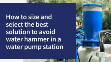
How to size and select the best solution to avoid water hammer in a water pump station
Play Video
Published on
Presented by Colin Kirkland
Join Bermad Water Technologies Air Valve and Product Manager, Colin Kirkland, in this technical training seminar on how to avoid water hammer in a water pumping station. In this presentation, learn more about:
- Understanding the problem of water hammer
- What information is needed to best determine a solution
- How to analyse data to determine a potential solution
- Column separation air valve solutions
- Minimising the impact of daily surges
- Preventing issues from power failure
- Using fast acting pressure relief valves
Content
Transcript
Hi, welcome to another video technical seminar by Bermad Water Technologies. My name is Colin Kirkland and I’m one of the engineers at Bermad. The purpose of this video demonstration is to really talk about water hammer in pumping stations. We want to give you a little bit of advice on 30 years experience that we’ve got, looking at lots of problems that happens at pump stations and pipe networks where water hammer occurs at these locations.
And what we really want to do is share some information and share some knowledge of some of the potential solutions which we have, which may be suitable for your location. So this is designed for designers, operators, users, anyone who’s working in a pump station in mining irrigation, water supply, or in buildings where they potentially are having issues or surges at pump stations themselves. So, with all that said, let’s get into the content.
What we’re going to discuss a little bit about in this seminar is really understanding what the problem actually is in the station itself. In many instances, it can be quite complex, really trying to understand why that solution is coming.
So we want to really try and get a lot of information to really understand where the problem is actually coming from. With this information, what we really want to try and determine is once we’ve gathered a lot of information on how the pumps work, what they do and their function and understood something about the hydraulics, we can then potentially come up with a solution that might be suitable for the problem that occurs.
Now, one of the key things about getting this right, is really analysing and getting very good data on what the pump performance is, the application, how it works, how the pumps ramp up, how the ramp down and generally what the issues are. So we’re going to be asking a lot of information about what’s actually required.
Um, once we’ve got all that data, we’ll talk a little bit about column separations. So that’s one of the potential problems that can occur in that pump station. If power fails or something goes wrong, we’ll discuss a little bit about what column separation is and how we can best utilise that situation to mitigate the surge.
We’ll talk a little bit about what we call a pump control type application. So this is a product that’s going to stop the surge happening in the start, but we need to know that it’s compatible with the pipeline and the application. So we’ll talk a little bit about that too as well.
We’re going to talk about something that occurs if there’s power failures. So if a pump was to stop in an uncontrolled mode through power failure, or losing prime in the suction or something like that, we want to talk a little bit about surge anticipation. That’s one of the options which we have to try to mitigate that search in the event of an uncontrolled pump shut down.
So we’ll go into the ins and outs about what we do there. We’re also going to talk a little bit about fast acting relief valves. So, so why would we use a fast acting relief valve as opposed to a surge anticipating valve? Is it about the pipe length? Is it about the pump station, how it ramps up? So we’ll talk a little bit about the engineering and the hydraulics on why we would use some of those.
So let’s get right into understanding the problem. So, in many pump stations, what generally is happening is, is that the pump is going to ramp up and it’s going to provide flow to a reservoir, a tank, an irrigation system, a mine, whatever.
But what we first need to understand is a little bit about what is the problem that’s happening? And is this problem happening when a pump starts. Now, if we’ve got a pump with quite a steep pump curve and the pump starts very quickly, it could well be that we’re over pressurising the pipeline when the pump first starts, because we’re running the pump back on the curve or generating a lot of pressure above the normal working pressure of the pipeline.
So it may be that pumps start as part of the problem. And that’s important to understand. We want to know if the water hammer is happening on shut down. Now, on a pump shut down there’s many ways in which a pump is going to turn off.
There may be a drive where the pump is going to ramp down electrically over a slow controlled period. There could be a control valve that shuts down generally, or it could just shut down instantaneously. So if we know that we are getting a return surge that’s coming back to the pump station when the pumps turn off, that could be something really important to know. So we’re trying to understand if that’s the issue, then we might have a solution that might be able to find and fix that problem.
Now, if when the pumps are ramping down, that there is no surge because we’ve got a controlled mode of reducing the velocity over a controlled period. Not a big issue, but what if we have a power outage? What if the power fails or if it’s on a diesel pump it runs out of fuel very quickly, and the pump stops very quickly. In that condition, that’s an uncontrolled shutdown. So if that’s the situation, then we know we’ve got a solution to satisfy that requirement too, as well.
Now, if the problem trips under high load, so for example, the more flow that we pump, the more energy we require from the motor. So in some instances we might be running for example, at 100 litres a second. But there could be a situation where the demand and the network is drawing 120 litres a second. And under that condition or drawing too many amps, the motor is overloading and it might just trip and turn off. So if we understand that situation, then we know that what we want to do is actually stop the pump going into an overload condition. So again, that’s another possible solution that we might want to understand.
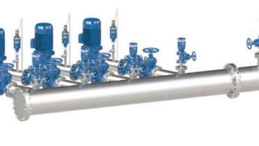
Now sometimes we really need to determine, this was as shown in the picture there, this we’re just showing a single pump. But in many stations we might have multiple pumps. So we could have two pumps that are duty and standby, or we could have three pumps. We could have two that run, and one is a standby unit or three.
And in many cases there’s multiple pumps. So we need to understand that and to understand that is the problem happening when we’ve got three pumps running, is it when all three pumps turn off at once, or is it when two pumps ramped down, that’s all fine, the last pump that turns off?
So we’re trying to understand if there’s multiple pumps in a station. Where’s the problem occurring and it could well be that it’s simply just a control issue and it might not even need a valve, but, um, we just need to understand a little bit about where it’s happening if there’s multiple pumps in the station itself.
Now in some instances, there can be problems with the priming or the inlet side of the pumps, where they may lose their prime for whatever reason. And when they lose their prime, the pumps basically turn off very quickly. So if we understand that, then there could be some solutions that we may have to address the pumps stopping, going into losing its prime in the suction side too, as well.
So it’s really important that we understand some of those things and we understand where the problem is coming from, and then get the right solution to actually come up with the best, the best solution to fix the problem.
Okay. So let’s get right into the information which we would need. So if you were coming to us and saying, “Hi Colin, we’ve got an issue at a pump station, we’re generating some surges.”
What do we actually need to know? First thing is, we need to have a general idea of the pump station design. So this is, for example, it’s in a mine, we’re de-watering, or it’s a large transfer pump in an irrigation system, or transferring water to a dam, et cetera, et cetera. And we just need to get a bit of an idea of, of what the pump station is, how many pumps there are and what it’s general sort of function is.
The water quality we’re using is very important to understand. So, for example, if we were in a mine and we had varying water quality that we were transferring out of the mine, we want to know that the pump, the valve is going to be suitable for this. We want to know if there’s solids in it, we want to the pH, the temperature. So water quality is very important because we need to make sure that everything is compatible for the solution that we’re going to go with.
Number of pumps and how many can run at one time is critical. We need to know that because that’s really determining, you know, if we stagger the pump ramp up or ramp down, it’s going to have a considerable effect on the water hammer.
We really need to know what the individual pump performance is in flow rate and pressure. So nearly all pumps have what we call a pump curve. So it’s really good to see what the pump curve looks like. That really gives us an idea of how much, flow and pressure it’s going to develop at different stages of its RPM and, and how it’s kind of going to work in an overall package.
Motor speed is critical. So if we’re talking about a two pole motor pump that runs at close to 3000 RPM, as opposed to a four-pole pump that runs 1440 or a six pole pump for example. Why that’s important, because the pumps generally have a certain amount of inertia. In other words, they’ll run on for a certain period of time when they switch off.
And typically we find that the greater the number of poles or the slower the RPM and the pumps, the slower the pump will ramp down. So it’s important to understand a little bit if we’re using a diesel driven unit or, um, or an electric motor driven unit and what the motor speed is too as well.
Now, this may be an existing pump station and you may already have a system that designs to ramp the pumps down without soft start or a drive or something, a electrical, um, device that’s going to control the rate of ramp up and ramp down. So it’s very important for us to understand, you know, if that’s what you’re doing and over what period are you starting and stopping those pumps so that we get a bit of an idea of what’s going on.
Now really importantly, the pump station is one aspect of it. It’s imperative that we understand what we’re pumping into. For example, it’s imperative that we know, let’s just take, say, take an example of, as I’m transferring water from a river, three kilometers to a dam. We want to know the pipeline diameter. We want to know it’s PN rating. So we want to know that it’s running PN six poly, um, over six kilometers.
So we really understand the pipe diameter, the type of pipe that it is, whether it’s steel, poly, PVC or whatever. Because what this does, if we understand the network and where it’s pumping into, we can get a very good idea on what that return surge is going to look like and how fast it’s going to return. And do we have a solution that’s quick enough to respond to it?
So getting that information is really critical. But really importantly, at the end there, we need to understand the static head. So what we’re referring to there, is that if the pumps were all turned off, we need to know what the static pressure on the discharge side of the pump is with the pumps turned off.
So, for example, let’s say we’re at elevation 100 at the pump, and we’re pumping to a tank at elevation 200. We know that we’ve got a static pressure of around about a hundred meters. So, it’s very important to gather that information, because this really gives us the ability to do some surge analysis and really check and see what’s going to happen in the network. And importantly, at the pump station too, as well.
Okay. So let’s just, I’ve just given an example here on the top right-hand side of the screen, where we’ve got two pumps, um, that are producing each 80 odd litres a second, developing 75 meters of head where they’re running at 1440 on four pole. They’ve got a soft start that ramps up over 5 seconds and they’re pumping into a 300 millimeter steel main over around about 5 kilometers with around a 40 to 50 meters static head.
That’s just a snapshot of a very simple application, but I’m just trying to get an idea of what we’ve got. Here we can see in the bottom right-hand side a typical pump curve of the pump that might be producing that energy. We like to get that information, but what do we do with it after we’ve received it?
Now, what is column separation? Column separation is when we turn a pump off, and the pump has been running at 75 meters. If we watched the pressure gauge drop to zero, or if we see the pressure drop below zero, we’re going to have air being drawn into the pipeline.
So what tends to happen is is that the water basically separates. The pressure inside the pipe drops below atmospheric pressure outside. And if there’s an air valve present, it’ll basically draw large amounts of air back into the pipeline.
Now, why is it important to know this? Air in a pipeline is compressible. And because it’s compressible, it can accentuate the water hammer. But if we have air coming into the pipeline and we control, we allow large amounts of air to come back in, but control the rate in which we let it discharge; we can possibly utilise that air as a very good cushion to ensure that we can actually mitigate the surge on return wave.
So column separation is when we have pressures dropping below atmospheric pressure, going into negative pressure or vacuum, air coming into the pipe, and then air comes back out. It’s a problem because if we don’t control the rate that it goes back out, it’s going to make the water hammer worse. So if we fit a conventional air release valve at the pump station in column separation, a conventional combination air valve that lets air in very fast and lets air out at almost a similar rate. The air valve itself potentially will make the water hammer worse. Because if we let the air out very, very fast and then it comes up to a static condition or generating a rapid change in flow, and that’s going to accentuate water hammer. So there are types of air valves, which we’re going to get into a little bit later, which can really ensure that that doesn’t happen. But we’re going to use this as a really good tool to mitigate that surge.
So how does it achieve surge mitigation? In very simple terms, the air valve lets the air in very, very fast. But it lets it out at a very slow controlled rate. And when it lets out at a slow controlled rate, it means that the water column coming back to the pump station comes back very slowly. So utilizing that air bubble, you know, there’s sorts of things that happen when it does that, but that’s what an air valve can potentially do to mitigate a lot of the surge.
So there are certain installation tips and considerations that are really important when it comes to putting those types of air valves in. We don’t want to oversize them. We want to make sure the orifice is correct and is suitable for the application. We want to make sure that the pumps don’t restart before the air is discharged and the locations of them are critical. So we have more than 30 odd years experience in knowing where to put the air valves, where to, exactly the best location to have them, what to make sure that isn’t around it.
Sometimes there’s additional air valves there that make the problem worse. So we’ve got lots of experience in really knowing how to do that. And that’s, again, it’s a topic for another day, but we’ve got that experience to show you where to put it and why.
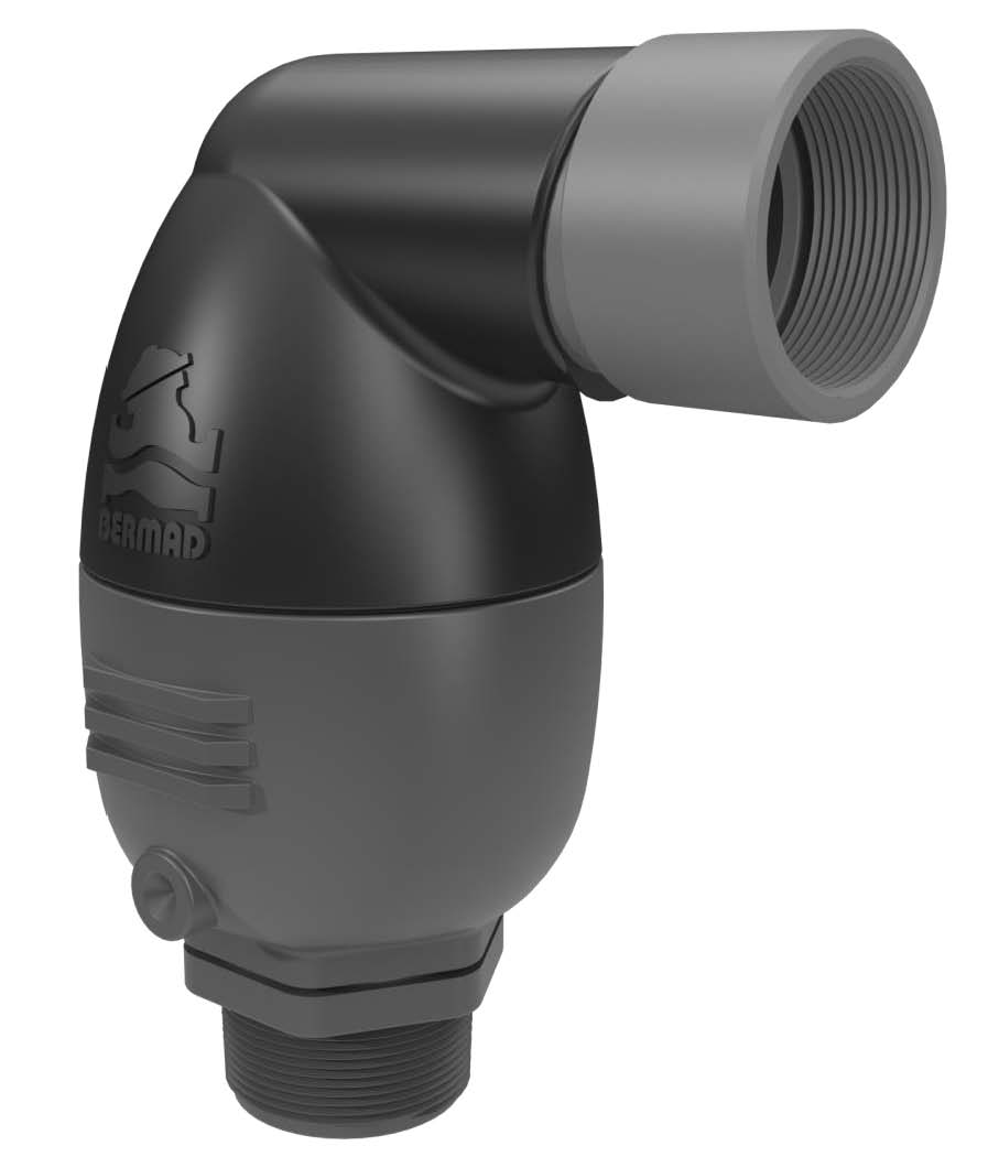
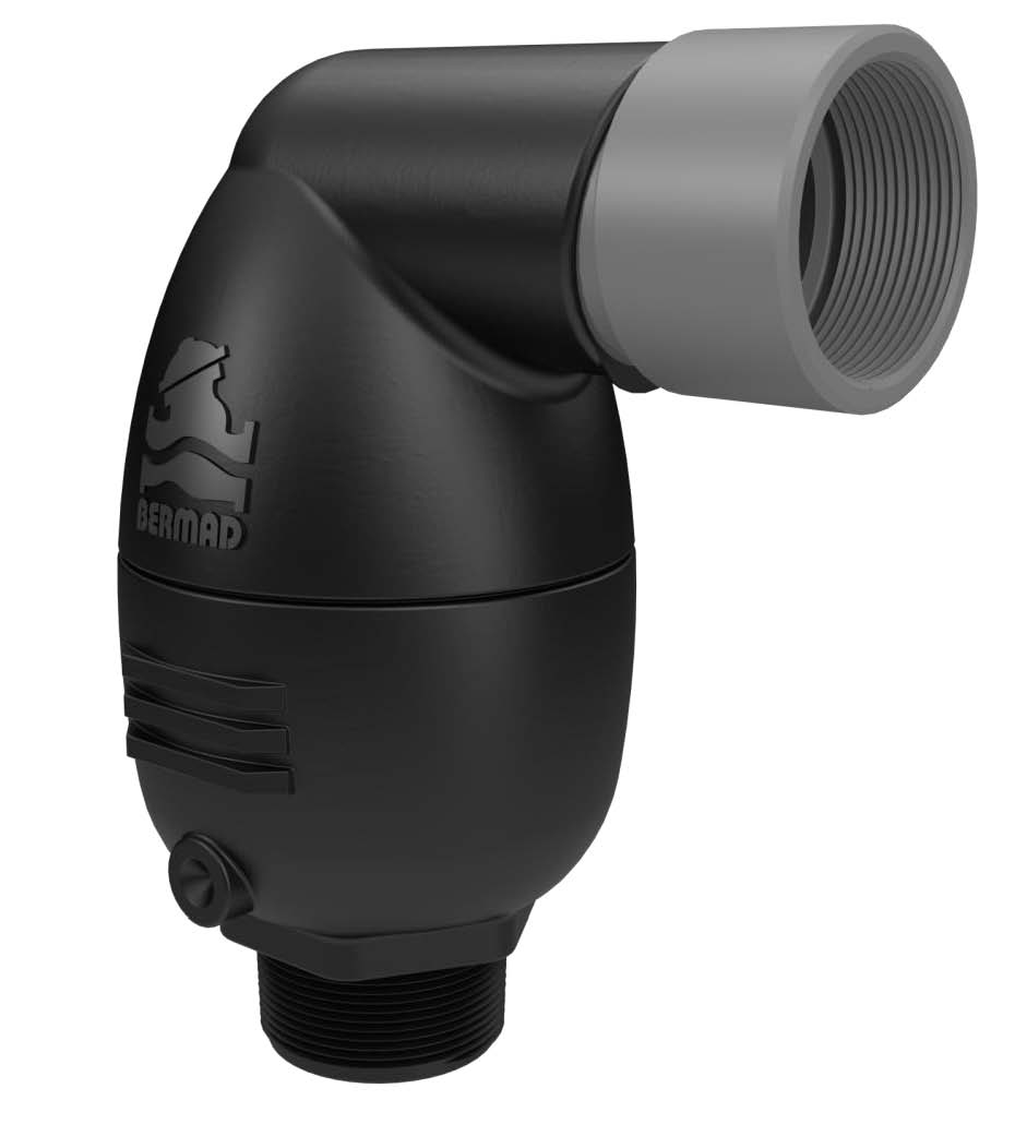
So let’s get right into the nitty gritty. What are some of the types of air valves that we can utilize to do that? Here we’re looking at the Bermad C-10 or model C-30 valve with SP. What we mean by that is with surge protection. So this valve does precisely what I was talking about before. It’s a very high capacity air release valve that will allow large volumes of air to come in. We have them in DN-50 and 80, two inch and three inch air valve sizing that will allow larger volumes of air to come in, and control gently the air discharge to use that air pocket.
We can see the air discharge curve on the bottom right-hand side there. And we can see if we follow the blue line, we can see that the air is compressed very slowly in discharge, which is exactly what we want. So this product is basically either a PN-12 or PN-16 type product.
So it’s designed for low air pressure pipelines of maybe up to 300 to 375 diameter pipes maximum possibly. Flows in the pipeline around 100-150 odd litres a second, roughly, but this sort of product is very simple. It’s a beautifully engineered product to really mitigate that return surge, carefully and at a controlled rate.
So it’s something that’s designed for also dirty water. It’s a good product designed for, you know, river water, drinking water too as well. They’re Australian standard approved AS4956 and they’re proven design that can work. And really importantly, they can be modeled. And so what I mean by that is that the valve can, the valve data can be entered into proper surge analysis programs that can give you an idea of what’s going to happen, not just by gut feel, but in actual practice before they’re even mitigated. So very good, simple product only in two specific sizes.
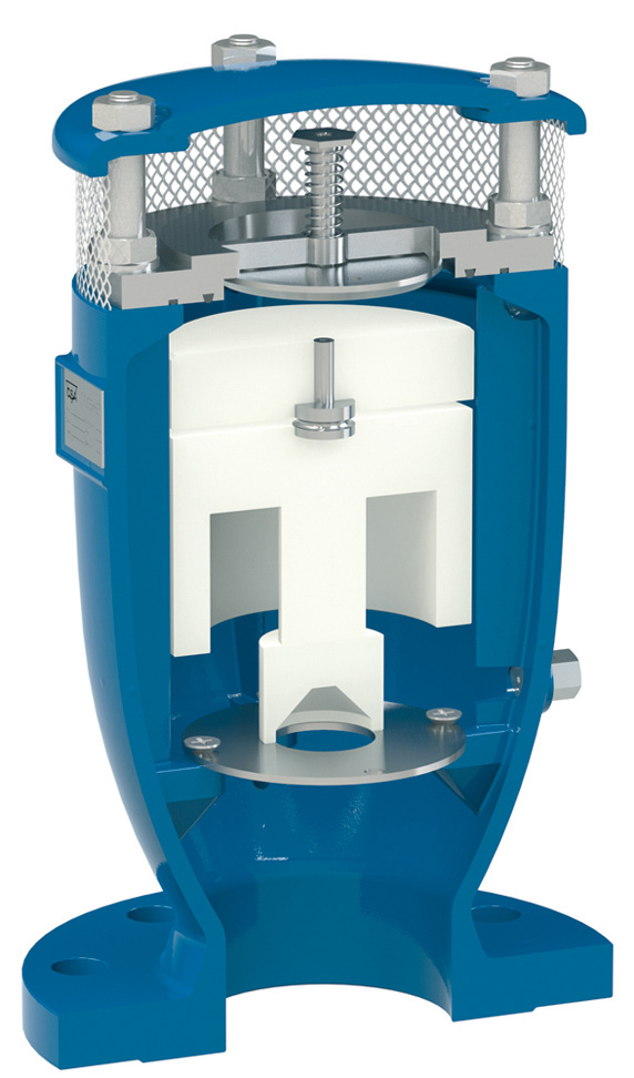
We also have the CSA Fox anti-slam air release valve. Somewhat similar in design to the Bermad product, but this basically, instead of having a slow closing cushioned surge protection mechanism, this basically has, if we were to take for example an 80 millimeter air valve, it would have an 80 millimeter air intake. So large amounts of air in, but it may only have, from memory here, right about a 10 millimeter air discharge orifice. So large amounts of air in very slow controlled air discharge. The Fox anti-slam valve has been used in Australia for many years, 15-18 years with great success, very accurately modeled in search analysis programs available from 25 mil up to 250 millimeter in size.
The benefit of this product is that we know we can use not only class 16, but class 35 valves too as well, if it’s a higher pressure pipeline, and pipe diameters right up to 1.5 meters and greater if need be. The product really is a ductile iron fusion bodied poxy. It has 316 stainless internal components. And one of the unique things about this is that we can actually modify the discharge orifice size to determine how fast we want that air bubble to return. So if we found that it was working a little too slowly, we can open up some orify in there, and make it a little bit faster or vice-versa, we can slow it down.
So it’s a really proven good solid product, critical where it goes, and critical that it’s not oversized. And again, as I was explaining in the past, it’s not just about the product doing it, but making sure that we’ve got correct isolation on it. We’ve got it at the right location where the column separation is going to occur.
One of the critical design things with the Bermad and CSA is that these valves must be installed downstream of the pump check valves. So this is the location where we’re going to see some atmospheric pressures. So the location of them is critical. And again, we can assist you with, if we’ve got some idea of the pump station design, where to locate this at that point.
Now, ideally the pump station, but both of these products can also be used if there’s column separation on the pipeline. So two kilometers out, et cetera, too, as well. And again, we can give you that advice on where best to locate those products on the pipeline itself. So now we’re going to talk a little bit about a situation that occurs at the pump station.
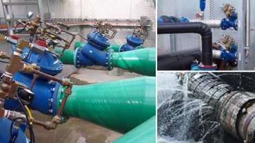
So if you look at a couple of these pictures that you can see in the installations in the bottom left here, it was a water authority where we were pumping water at 200 litres a second up through a transfer pipeline going to a reservoir. If you find you’ve got a pump station where the static head is somewhat similar to the dynamic running head, it means that it can be quite challenging to generate a gradual increase and decrease in flow by using electrical drives. Because basically if the difference between the static head, let’s just say the static head was 75 meters and the running head was 80 meters. Well, the pump is only going to displace any flow once the pump has ramped up to the condition where it generates more than the static head, more than 75 meters. If this was the case, it might ramp up to 48 Hertz, and then finally, the last two Hertz it just opens and creates that sudden change in flow. Same thing for ramping up and ramping down. So just to repeat, if we’ve got a situation where the static head is somewhat similar to the dynamic head or close, a pump control valve is a really good option here to put at the pump station.
So what is a pump control valve? Well, it’s basically a valve that sits on the discharge of the pump. Now first of all, it’s a non-return valve. So we generally don’t like having an additional non-return valve in the pump station. Now most pump stations have a check valve or a non-return valve to prevent reverse flow.
The Bermad 740 valve being double chambered is inherently a check valve, that’s number one. The second thing is what the pump control valve does is irregardless of the speed that the pumps starts, once we generate more than the static head and the pump has started, we energize a solenoid on the valve and the valve opens slowly.
So for example, the picture on the bottom left-hand side was running around 200 litres a second, roughly 300 millimeter valves I think from memory. We were opening and closing those valves over around about two to two and a half minutes. The net effect when you use a double chambered 740 pump control valve is they work in a linear fashion.
So what we mean by that is you’re going to see a nice gradual increase in flow as the pump starts, and you’ll see the flow increasing at a gradual rate, minimizing surges. But really importantly, when the pump has to turn off, the pump signal says to the control valve, keep the pump running, but make the valve turn off.
So we de-energize the solenoid and the valve starts to close at a very slow controlled rate. And as that, so the pump is still running, the valve is closing at a slow controlled rate. And once the control valve gets to 90% closed or 95% closed or getting close to zero flow; we have a micro switch on the indicating shaft there that then tells the pump it’s safe to turn off, we’ve reduced the flow and no surge. So in short, a pump control valve is a valve on the discharge side of the pump that will open very slowly, it will close very slowly with the pump running, and turn the pump off. The net effect – it minimises the surge through standard ramp up and ramp down irregardless of how fast we start and stop the pump.
So it’s really good in that instance, there, the situation in the middle there in the picture was at a pumping station where it was very, very sensitive older mains. When the pump started and stopped, we used to get transient pressure waves that would break the pipe. Those pump control valves have been in now for something like 18 years and work all day every day, ensuring that the pumps are not the issue that generate this transient surges in the pipeline. And again, the situation on the bottom right was exactly the same, a very old aging network of pipework that was sensitive to pump starts.
So we put pump control valves and they’re working really well. So the pump control valves themselves from DN50 to DN600, they’re basically the flanges that are either PN16 or class 35, and they fit exactly on the pump discharges and as shown here, slow opening, slow closing, fully adjustable of course to the situation. A good thing with this valve, as well as being it’s a non-return valve, we can add additional functions.
So for example, we can add a sustaining function to the valve as well. What we mean by that is that if part of the pipe was empty or if there was potential the pipe was going to run to a variety of locations, we may want to stop the pump running off the curve or running to an excessively high situations so we can put a sustaining function. We can also add a reducing function if they want. So there might be an application where the pump is running at full motor speed, but we don’t want to get all of the pressure out under some conditions. We may want to bring that down so we can use reducing.
We can also put flow control functions, so we can basically say, look if the demand and the network was too great, and the pump was starting to run out on the curve where we’re drawing a lot of current from the motor, we don’t want the pump to run off the curve. We don’t want the pump to trip and high load so we can put flow control functions.
So it’s a really a box of old tricks here. The valve can do multiple functions in mitigating the surge and also controlling the network flows and pressures quite easily. And it’s adaptable. So a very good proven product that’s worked over many, many years. That’s the Bermad model 740 pump control valve.
Okay, so the pump control valve or the drive or whatever you’re using, works really well under controlled start, controlled shutdown. And that works really well. But what if we have a situation where once a year, twice a year, we have a power trip because of, you know, a lightning strike drops the pump out or has tripped on a high load, has lost its pump suction, and we get an uncontrolled shutdown.
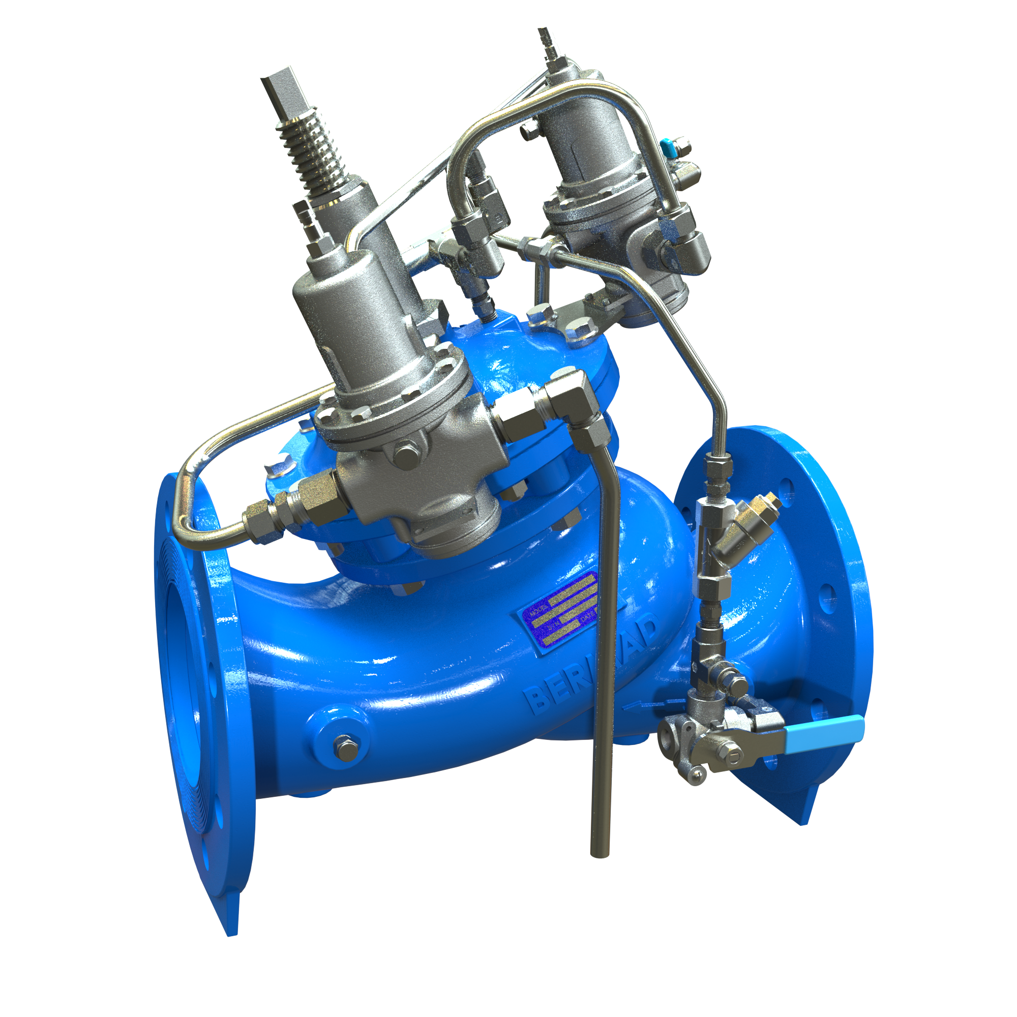
This is probably usually quite a rare event, but it’s something that’s imperative that you really plan for. So there’s devices like surge tanks, pressure release valves, surge anticipating valves. The Bermad 735 surge anticipating valve is proven over more than 20 years I’ve been utilizing hundreds of these throughout Australia with great success.
To size it, to install it and to know what it is. It’s basically a hydraulic fuse that is on a T piece off the discharge of the pump that basically says if the pressure goes high, I want the valve to relieve some pressure. But really importantly, if we have an instantaneous dropout we want, and we see a low pressure wave coming back to the pump, we want this valve to open on low pressure and anticipate a high pressure returned surge coming back.
It’s a very proven product that can be modeled on all modeling software today. In many cases like shown in the right-hand side there, we’ve got two, I think there were DN200 control valves set at slightly different set points. It’s a product where we know typically how much flow we want to dissipate to mitigate the surge.
Typically, it might be somewhere between 20 to 30% of the design flow and we’ve got flow stems on here. We’ve got two pilots that not only open on high pressure surges say on a pump start for example. But it has the second pilot that will hydraulically open on a power outage. So the good thing about this product is that it’s purely hydraulic. It doesn’t care about battery backups and power. It’s a hydraulic fuse to say that if we have a power outage condition or on pump shut down, we generally always see a surge; we want a valve that opens and takes out that excessive pressure and relieves that back to the tank or back to the river or a pressure source quite comfortably.
So the size of the valve is critical. Knowing all that information we spoke about in the start – sizing, understanding the pipeline, understanding the static head, the running head, the pipe material. Pipe material is critical because it’s going to give us an idea of the wave speed, whether the wave speeds going to be more than a kilometer per second, or 200 meters a second if it’s a poly pipe or steel pipe, you know. So it’s really important to get that information, but this is a really good proven product that really understands it well. It works very well in combination with surge protection or anti-slam air valves because there could be vacuum at these locations too, as well.
The valve is basically 50 millimeter up to 600 millimeter. We use them in very big pipelines. Again, the flange connections PN16 or PN35, they’re always fitted on a T branch off the discharge of the pump station after the pump check valve. So it’s not before the non-return, but it’s after the non-return because we want to avoid the return surges coming back and hitting their pump stations.
So a really good proven product, and we can come up with multiple ideas of how we can do this quite straightforward. Now there are several options that we can add to this valve too as well. If we have, for example, a pipeline topography that’s highly undulating and really a very long pipeline, we may want to add solenoid to this function to enable the valve to stay open for a certain period of time, but there are several options that we can do here. The good thing about the Bermad 735 is it’s proven. We have hundreds of applications in multiple applications, mining, irrigation, water supply, in building or not so much in buildings, but in more larger transfer pipelines.
And it’s really proven. And the fact that it can be modeled, gives a lot of comfort and security to whoever is going to use this, to know that it’s going to be safe when we need it. So again, utilise our experience to really show you how we do that. Now in some cases, if we’ve got different applications, like for example, in the left-hand side here, we’re at a mine where we’ve got bore pumps. And when the bore pump starts, we tend to have some of the pipe is empty. And when it finally hits the pump of check valve, we get very high spikes that happen very quickly and we sometimes want a very fast-acting hydraulic pressure relief valve that lets these spikes out nice and fast and shuts down nice and gradually.
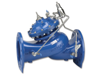
So we have the Bermad model 73Q, which is a fast-acting pressure relief valve. And again, multiple sizes where there tends to be used at pump stations where if something goes wrong, for example, let’s say something electrically went wrong with the drive and we’re working on a variable speed drive, but the sensor went wrong and all of a sudden it started malfunctioning and we’re getting excessive pressures; this file is going to open fast, dissipate that excessive energy, and shut down nice and gradually not to avoid a second resurge.
Sometimes our quick acting relief valve in different applications with the middle picture here shows our multi-stage centrifical pump where there’s a very steep curve when the pump starts, we get a very quick pressure spike. We might want to take that away very quickly. 73Q is ideal for that. And again, we know how to size it. PN16 and PN35 flanges again on a T piece after the pump can be before the pump check valve, but generally it’s afterwards, but, it just depends on the specific design of the pumping station itself.
But another valve which we have is the CSA VR CA. Now, in some applications if we have a very small length of pipeline, let’s take the example where we might only be running 600 or 700 meters in a 600 millimeter pipeline to an open discharge. Now, when the pump turns off in a steel pipe, we might see that that return surge comes back to the pump station in 0.6 or 0.7 of a second. So it’s very, very fast.
So to put in a pilot operated control valve, we can make those valves work exceptionally fast, but sometimes it’s a little safer and simpler to use what we call a direct acting type relief valve like the CSA VRCA valve. Now this is basically a direct acting very fast opening pressure relief valve. It’s exceptionally fast in response rate depending on what the pressures are, but the CSA valve is really good for taking out transcience.
So we’re interested in taking the tops off high pressure very quickly. And this is precisely what this does. So for example, the application on the left-hand side was an application where potentially, we were going to see some very fast traveling pressure surges, and the client wanted to put some bursting discs in. Bursting discs is wonderful for taking out high pressure, but once the bursting disc brakes, it stays open and drains the pipeline.
So in this application on the left, we basically had a bursting disc at 190 meters. Then we had some fast-acting relief valves at 185 and 180 meters. So we want to avoid the bursting disc going off, and have something that quickly gets rid of that energy. And if all was catastrophic, the bursting disc is always there.
So a VRCA fast-acting relief valve is wonderful for taking our transients, and really good for very sensitive old networks where we don’t want, you know, even 5 or 10 meters of rises, too excessive. And we want to just make sure we take the peaks off any of those potential transients and at a pump station, we’ve often fitted this product, which really has virtually little, if any maintenance at all. Very simple, really important we size it correctly. In some cases we’ll put multiple valves at slightly different staggered set points if we want to get rid of different volumes because we’ve got multiple pumps, et cetera, but it’s a really proven type design from 80 millimeter up to 200 millimeter, classes PN16 or PN25. And again, usually fitted on a T piece down stream.
Where you put these control valves is really critical. I can speak for a long time about where to put them and how to put them at different cases. But that’s another story it’s best that you contact us and really we look at your individual design and look where that transient is going to happen, and release it at the best location that’s not going to allow it to mitigate along the pipeline.
So there’s a lot of experience in knowing where to put it, how to install it, how to make sure it’s safe for an operator. So for example, the designer on this location on the left did a really good design that enabled an operator to come to the valve, safely close the valve without getting wet or being dangerous and allow that energy to dissipate to atmosphere very quickly. You know, so really good proven product again, can be modeled in all those sizing softwares, and really designed for transient relief in pump stations and or along pipelines and stuff too.
Okay. So in summary, we’ve only described a few solutions which Bermad offer for mitigating surges at pump stations. Of course, there’s multiple solutions. There’s surge tanks. There’s one with surge tanks and there’s multiple things. We as a valve supplier and as a meter supplier, I’ve just given you some of the history over 30 years where we’ve been utilising these products with great success.
There’s no simple solution to a product. But the best way that we’ve always overcome these issues is really to understand water hammer, to understand the pipeline and not just putting a quick bandaid on, but to really understand that information. So doing your homework, getting all of the information about not only the pumps, the pipeline, the application, how it’s being operated, really tells us the whole story, which gives us an idea to give you a good solution that gets it right the first time.
You know, so really do your homework, try and figure out what all that is and really get it well. Critically and really critically, and we’ve spoken about this in many of our podcasts and seminars and stuff before is that all of these tools and products and everything else that you use are great, as long as they are properly commissioned, correctly sized and operators are trained in their operation.
You know, there’s nothing worse than having a product that you put on there, you walk away from it and the operators have no idea what they’re doing with it. And they’re nervous about it because they know that it’s a critical part of infrastructure.
So one of the things which we do so well, and is, to our understanding, is critical for not only day one when you’re supplying the valve, but in 10 years and 20 years down the track, is training operators. Giving them good tools, like YouTube videos, like tutorials, on-site training, bringing people to our facility to actually tell people how they work, why they work, why they might fail, and how to prevent them failing.
Education on anything to do with search mitigation from day one, till the day it’s in the pipeline is critical that not only the engineers operators and people that are using it really understand that. So that’s what we do exceptionally well and utilise it. This is what Bermad’s strength is, in really making sure we get these long-term solutions working well.
So, if you do want to see or look at any of those tools that we’ve got, go to www.bermad.com.au, or go to our YouTube channel to see any of that sort of product and stuff too, as well.
So in summary, I really appreciate you taking this time to watch the seminar. I hope you got something from it, and if you have an issue or a design in the pump station, you know where to find us. Thank you for watching.
-

Colin has more than 40 years’ experience working in water supply and irrigation in Australia, including 24 years with BWT. He credits his training at Weir pumps in his native Scotland for providing him with a solid grounding in engineering.
Colin is a mechanical engineer and a fitter and turner, who prides himself on taking a hands-on approach when designing and implementing successful installations across all aspects of BWT’s products and markets.
Read more about Colin: Who’s who at BWT – Colin Kirkland
Products
 View product
Fox 3F AS Anti-Slam Air Release Valve
 View product
WW-73Q Quick Pressure Relief Valve AS5081 / WaterMark
 View product
IR-C10-P-SP Combination PN12 Air Release Valve with Surge Protection, AS4956 approved and WSAA
 View product
WW-C30-P-SP Combination PN16 Air Release Valve with Surge Protection, AS4956 approved & WSAA appraised
 View product
WW-735-M Surge Anticipating Control Valve Watermark & AS5081
 View product
