UL listed deluge control valves for use in Australian road tunnels
Play Video
Published on
Presented by Colin Kirkland
Join Bermad Water Technologies Air Valve and Product Manager, Colin Kirkland, in this technical training seminar on UL listed deluge control valves for use in Australian Road tunnels. In this presentation, learn more about:
- Tunnel design challenges
- Objective of deluge spray system
- Typical tunnel designs
- Importance of the deluge valves
- Engineer challenges of the deluge valves
- Bermad fire deluge valve range
- Bermad’s history of Australian tunnel deluge systems
Content
Transcript
Hello, and welcome to another technical video seminar by Bermad Water Technologies. My name is Colin Kirkland and I’m one of the engineers at Bermad. The purpose of this presentation is to talk about fire suppression deluge valves and their inclusion in Australian tunnels under fire protection. The video is really focused at engineers or anyone within the fire industry designing, operating, or using deluge valves within any tunnel designs, which are being incorporated in fire systems. With that being said, let’s get into the content.
One of the first things we really want to talk about before discussing the valves in detail are tunnel designs and challenges. The tunnels which have been used in Australia have changed over a variety of years due to their length and complexity. And we’ll talk a little bit about some of the challenges which designers have when incorporating some of these valves and will go into it in a little bit of depth.
We’ll talk a little bit about the deluge valve itself. So what is it? How does it operate? What is it’s function? What are some of the challenges and what are some of the engineering concepts, which are really important when considering the inclusion of it, the sizing of it, and how it’s going to operate. And we’ll talk about some of those challenges as well.
We’ll specifically talk about three different types of Bermad deluge valves. We have what we call the 400E, which is one of the original valves, which we’ve had. We’ll then talk about the model 700E, which is another model with a similar sort of functionality, and also the 400Y, which is our new torrent valve, where it’s being used highly in a lot of the more frequent tunnels that are around today.
We’re also going to give you a little bit of an overview of some of the history of where we’ve used valves in Australia before. We’re going to show you some of the technical reasons why some of these valves were used, and some of the hydraulic conditions that we’re operating in, so that if you are looking at a tunnel design today, you can see, well, this has been done in the past. You can see they’ve got history and you can see that the flows and demands of their valve are achievable. And they’re actually being used presently in this format.
Okay, let’s get into some of the designs of the actual tunnel itself. The picture you can see in the right here is very close to where I live. There’s a tunnel being designed in the area of Rosana and going through to Berlin. And when you consider what’s actually happening in a tunnel, so this particular tunnel being designed is six and a half kilometres. When we are tunnelling under all of the infrastructure and the houses and the rivers. And if you look what we’ve got here, we’ve got parks, freeways, residential areas. There’s a lot of challenges that the engineers have got. And basically the longer the tunnel is, the more you actually have to channel further down and deeper to miss a lot of the infrastructure, which is currently there.
There’s a lot of challenges facing engineers when they are designing these. But, it’s basically ensuring that we miss all the infrastructure, which is sitting just below the ground level and on ground level, of course. Now, what’s happening today, is with the tunnel technology that’s happening, these tunnels are becoming deeper, longer, and the efficiency in which they can generate these tunnels is amazing.
What that generates for the hydraulic engineers who are actually designing these tunnels, is that all of a sudden now, instead of lowering maybe 50 meters below the ground, we’re going up to a hundred meters below or even greater. And those instances, those conditions generate a lot of challenges, hydraulically in pressure and flows. And it’s making life considerably greater. This is the Northeast link tunnel on Greensborough road, which you can see looking at the maps here, you can see the amount of infrastructure and roads and bypasses and everything has to do. It’s quite challenging of course.
Let’s get into the objective of the deluge spray system itself. Ultimately, the deluge system is a series of pipes and pumps where water is transferred through pipelines, and then there’ll be a series of valves, which will activate in the event of a fire. If there was a fire in a road tunnel and the fire detector determined that the valve had to open electrically, it will tell the valve it has to open. The valve will open and it will regulate the pressure, and it’ll go through to a series of spray nozzles that basically have to then suppress the fire and actually put the fire out. One of the key things about the deluge valve itself is that ultimately what it’s trying to do, is to ensure that we get exactly the right amount of flow and pressure to each one of those spray nozzles.
The sprain nozzle is an absolutely critical aspect of the deluge system because what we know is that if we over pressurise the water at the spray nozzle, the droplet size and the spectrum is going to change, and we’re trying to achieve a very specific droplet size and spectrum and a distribution to ensure that it covers the whole roadside. And of course, that the droplets remain at the correct level. Now when we have a tunnel, that’s going to vary dramatically in topography where there’s a whole variety of inlet pressures to these deluge valves; the importance of getting the right spray pressure coming off the valve is really critical. And that’s one of the things that the Bermad deluge valve actually does.
In addition to the valve actually opening and maintaining that pressure in the line, it has to do it under a very specific time. The key thing is that if the detector basically says it’s time for the deluge valve to open. When that valve opens, we want it to open in a very specific time, that is usually very fast. We want it to get the water up to speed very, very quickly. Get it through the spray manifolds, onto the spray nozzles, and onto the ground as quickly as possible.
There’s many challenges which we have as the valve manufacturer when they say we want the valve to achieve certain hydraulic conditions, we want the valve to open within X number of seconds. So it’s very important that we’re able to ensure that the valve and its trim and the way that we configure the valve has the ability to do that. Time is everything in fire suppression. If the valve takes too long to get up to speed and too long to regulate, we’re wasting time that could be saving people’s lives, ultimately in a tunnel.
In addition to the opening time, the closing time is really quite critical too. In these deluge tunnels of, you know, 4, 6, 10 kilometres long, there’ll be banks of deluge valves all along the actual tunnel itself. And it may well be that there may be different zones being switched on and off. Now some of the challenges to the tunnel designers is that the velocities that we are running through the pipes are extreme. You know, we could be running at 4, 6, 8 meters a second in there. And what we don’t want is when we turn these valves off, we don’t want to induce water hammer. Water hammer is going to happen because of a rapid change in flow. There’s very specific demands, which they have on the Bermad valve that might say, when we want it to close, we want it to close over 10 seconds or 12 seconds. If it closes quicker than that, that could potentially generate water hammer. It’s one of the objectives of the deluge valve that’s really quite important that it operates there. But regardless of all that, the point is that the valve has to be able to put the fire out in the tunnel, irregardless of where it is in the tunnel.
If we are sitting right up at ground level at the start of the tunnel, we have reasonably low inlet pressures. It still has to have exactly the same effect as if it’s right down at the very lowest part of the tunnel, where it might have 25 bar of water pressure there. It still has to perform exactly the same way irregardless of where it is in the tunnel. So that’s the overall objective of the deluge valve in the tunnel system.
Okay, let’s have a bit of a look at a snapshot of a general tunnel design. What we’re looking at here is ground level at the top, where we can see houses, rivers, parks, et cetera. We can see a pump on the top left hand side of the screen and a pump also at the top right hand side. And we can see the tunnel channeling all the way down in a U-type shape. And this is the main pipeline, which is actually transferring all that water down to these small deluge valve sections. So this is the manifolds, right at the different points in the tunnel, where all the sprays are and where the deluge valve is itself.
Here, we can see, as we are lowering down in the actual tunnel itself, due to topographic changes, we’re actually gaining in pressure through changing from an elevation of 30 meters down to 240 meters at the bottom here. The pumps at the start of the system are generating pressure and they’re producing pressure all the way down. Now, it’s quite challenging for the engineers who are designing these because ultimately what they’re trying to do is to get exactly the right pressure. Here I’ve nominated 300 Kpa, but it might be 400 or 200. But what they’re trying to do is to generate an exact amount of pressure at each one of those locations, irregardless of where we are in the tunnel design. So if we’re at the start or at the very bottom, we still want to maintain that. And this is the job of the deluge valve, to not only open and close, but to also regulate the pressure to maintain that 300 Kpa at the sprays. So that’s some of the challenges that we’ve got when we look at a typical sort of design.
And of course the big thing about these tunnels, which are happening today, is that the tunnels are, instead of being three and four kilometres, they’re eight and 10 kilometres and longer. So the longer the tunnel, the deeper these tunnels potentially are going to miss trains and all the other infrastructure and all the pipelines and everything underneath there.
These tunnels are getting deeper and longer all the time and generating quite considerable challenges to the designers of the tunnel fire suppression system itself.
So let’s talk a little bit about the importance of the Deluge valve itself. As I previously mentioned before, this might sound like a fairly basic thing to say, but the valve must open at a very specific time.
If that valve is delayed in opening, it’s delaying the fire suppression system and it’s a critical sort of thing. Reliability is everything. The valve must open every time, 100%. If it doesn’t open, the fire suppression system doesn’t work. So the design of the valve, how we configure it, how we filter the water and how we consider that the valve is going to operate, is really important to ensure that it must open every time very reliably.
Now, as I mentioned before, the valves have to regulate the water pressure. What we’re saying is that if we are at the lowest point in the tunnel and we have a water pressure of two and a half thousand Kpa, and we want to reduce that down to 200 Kpa, that’s quite a challenge. You know, the valve must be able to accurately and be stable, without over pressurising and without oscillating, be able to achieve a pressure reduction function irregardless of where it is. If we are right at the very top of the tunnel where we’ve got very low inlet pressures, it must be able to operate just as well, just as fast as if it is right at the very bottom of the tunnel where we have the very high pressures. That’s a really critical part of the deluge valve itself.
Now the valves have to be able to regulate at exceptionally high velocities. If we consider a typical pressure reduction valve that might work in water supply, it might be operating at water velocities across the valve of anything up to one to maybe two, even three meters, a second is an extreme. In a fire system, it’s so much more challenging. You know, we might be working at 4, 5, 6, even up to 9 or 10 meters per second water velocity in the valve. Now at those very high velocities, the valve has to be stable, has to regulate, mustn’t overshoot, must control that pressure really well and do it really well, irregardless of that sort of location that it is in the tunnel itself.
So it’s ability to do that is really extreme. And this might sound quite easy to achieve, but from a valve manufacturer, this is extremely difficult and Bermad have more than 30 years experience in doing this. And it’s really quite difficult to achieve, but absolutely achievable.
When I mentioned before, the critical nature of the whole infrastructure here, is that if we’ve got valves that have got something like 2000 Kpa, 20 bar of water pressure on the inlet side of the valve; we want the valve when it shuts down to ensure that it doesn’t induce water hammer.
If something were to fail in the infrastructure supplying these, that would be catastrophic, because then the system may or may not work. So it’s really important that when we are being asked for valve specifications of how they should work, why they should work, the rate in which the valve closes is very critical, and we are able to achieve those and actually demonstrate those complete opening and closing times and regulations very well to clients wherever they are in the world.
The valves must be able to withstand high inlet pressures with the valve closed 24/7, 365 days a year for 40-50 years. Now that might sound like quite a basic thing to say, what’s the big deal if the valve has just got high pressure in it and the valve is closed. Well, the thing is, the valve must be able to withstand exceptionally high pressures on the inlet side and zero on the downstream side.
Now the design of the valve is critical, that we don’t want a valve distorting on the downstream side. We don’t want to see a diaphragm rupturing because of exceptionally high heads that it’s being exposed to all of the time. The critical thing is that we’ve got so much experience in knowing how to generate the right product, which ensures that it remains drip tight sealed all the time.
Now I use the word drip tight there, because if you think about someone driving through the tunnel and all of a sudden, we start to see a valve leaking a small amount, and we start to see water dripping off the tunnel and dripping into the car. You know, you don’t want surprises when you’re in a tunnel, you don’t want things that are gonna frighten you, and leaking water. If you’re six kilometres into a tunnel, you don’t wanna be thinking about some of the ramifications. So without scaring people about it, we don’t want the valve to leak. And this is a critical thing with the Bermad valve, and why it’s such a good product, designed specifically for this type of deluge application. It has a great many years of experience where it does that, and it does it reliably 24/7.
Now on top of all that, if you are going to be selecting or wanting to use a deluge valve, it has to be certified to the requirements set out in the fire industry. There’s many companies, there’s UL, there’s FM, there’s many of those other organisations throughout the world that they use different accreditations.
When we are supplying a valve, everything that we do means that it has to be fully accredited to those demands. So with all of the regulating velocities, the reduction ratios and all of the things our valves must meet and be certified to those demands and they are, and that’s what we’ve done for over 30 years here in Australia.
Okay. So let’s get right into some of the engineering challenges, which Bermad find, you know, when we are coming to select a valve, when we come to do this. So, the importance, when I mentioned about the drip tight ceiling, these valves are tested regularly. They have to be, like any part of a fire protection system, this isn’t something that’s going to sit there. And look, we hope that this valve never potentially gets used, but it must be tested and it must be able to withstand the rigorous 24/7 conditions that these valves are going to be subject to.
The inner strength and the ability of that diaphragm to withstand all of those static conditions is absolutely critical. We want this product to work and work for many, many years without an issue. Now, one of the things that we know here in Australia is that after a certain number of years, there are certain components that are changed in some of these valves, just through due diligence, to ensure that the valves are fit for purpose and safe over a period of time.
But the big challenge from a valve manufacturer’s perspective is that it’s not only the ability for the valve to close and open, but it’s ability for it to regulate under these extreme hydraulic conditions. Now we might be talking about nine to one, ten to one reduction ratios across the valve at 5, 6, 8, 9 meters per second. Now, that may not sound terribly hard, but I can assure you, from a valve manufacturer’s perspective, this is extremely challenging. This is on the edge. This is really, and one of the things about Bemad is that we are a valve company. We are, today, the largest manufacturer of diaphragm actuated control valves in the world.
And we have a very dedicated fire department that know and understand this exceptionally well, and know the responsibility that comes with it when you’re actually making a valve of this for fire protection. It must work. It must be able to regulate regardless of its date and time of its operation.
So one of the things which we do when we are ensuring that the product is fit for purpose, is that we demonstrate this to a lot of potential clients. So if there was a client looking, for example, to say, you know, Colin, we’ve got a valve, we want to operate at 60 litres a second. We want it to regulate to 300 Kpa, and we’re going to have a variable inlet pressure from 500 to 2000. We know through our modelling software and through experience how our valves are going to work. But we like to demonstrate that too, as well. In this world of Zoom and Teams and all these sorts of meetings, we can do live on-stream testing and show clients where our valves actually operate and actually work on those operating conditions stably. And we can replicate that in our amazing facilities that we’ve got the factory to be able to demonstrate those. So a real big challenge for us is to ensure that the diaphragm for us is critical, as is every other aspect of the valve, but that’s the guts of the valve. And that’s the thing that has to work exceptionally well.
It’s ability to pass substantial flows. One of the things or the challenges that most of the engineers have, is that they’re trying to keep the infrastructure down to the smallest physical size that they can. When you’re tunnelling through a lot of infrastructure for 6 or 10 kilometres, size and room is everything. And the thing is, is that they’ll tend to use a lot of smaller diameter pipes. They’ll run them at exceptionally high velocities with high head loss. Why? Because of room, size and cost as well, of course is an aspect too as well. But the engineering challenge for the ability for the valve is to be able to extend extreme velocities and extreme regulation ability is very challenging. But we know precisely how to do this, and we know how to do it with a great deal of assurity.
The valves must be able to pass the codes, which are out there, including the FM and the UL. So not only do we believe we can produce a valve, but it has to also be accredited. It has to be certified and all of the components on there, on the valve and the solenoid, the strainer, the trim and everything to do with it has to be certified correctly to the UL or FM certification.
So it’s quite a challenge for us to come up with those. It’s not something that’s done very quickly. We have 30 to 35 years of experience in generating all of these certifications and everything else. We also have a dedicated fire team where all of their focus is really about maintaining and developing and creating the best product that can generate the best, safest product for them.
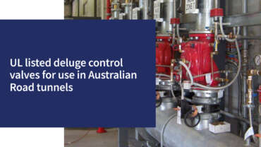
One of the key challenges in a tunnel I mentioned just briefly before was room. If you look at the picture that we see on the right hand side here, we can see three valves very closely put together, and here these are electric deluge valves designed to open electrically and regulate the pressure. Now, if we have a manifold of these, maybe five valves at a time or six valves at a time, when we are creating these areas where the valves are gonna be located, room is exceptionally challenging. So what the designers of the tunnel want is a valve that is exceptionally compact, fits in a very tight area, but is able to be serviced and maintained. For example, if you look at the picture of the valve on the bottom right hand side here, we can see the valve where we can see that the entire cover of the valve, where the four bolts are, is completely free from any of the control trim that we have on the side.
Now, why that’s important is that we know that after a certain period of time, we have to remove the diaphragm and we want to have access to the internals of the valve. So the point here is we’d rather not remove all the control trim if the control trim was on the actual bonnet of the valve itself. So here we can see the valve is exceptionally compact, very tidy, easy to get to, and the key components, when we look at it, for example, here, we’ve got the pilot regulator, the solenoid, the strainer, the manual emergency release to open the valve. All of those have to be accessible, close to hand, and easy to operate. Because if you think, if there was an emergency situation and an operator had to come down in an emergency and open the valve, we want access to that emergency release to be very good. So a lot of the designers are very, very specific about how the valve is trimmed. They’re looking at how the operators are going to use it and how we’re going to maintain it.
So it’s quite a challenge for us to come up with the right design that suits your right area. The good thing for us of course, is that we, because we have that dedicated engineering team, they can custom build each job to suit the exact requirements of the client to make sure that it fits within their area. So we’ve got the gauges accessible. We’ve got the strainer accessible, and all the other things that we can get to easily and make it easy to maintain. So that’s quite a challenge for us.
I’ve mentioned this a few times, and I can’t emphasise this enough, our dedicated fire team, which we have within Bermad have blinkers on. All they focus on is fire. It’s exceptionally important because they understand the needs, the requirements, the certification, and all of the criteria. When we talk about the certification, we’re talking about the QA. The test certificates, the documentation, the 3d drawings, all of that information is accessible from a really great team of people who are really dedicated to providing the very best solution for you, which might be completely different to what we used on the last job.
For us, it’s a challenge, but they’re up to the challenge and they do it exceptionally well. The other thing, which is not so much of an engineering challenge, but it’s more of a challenge for any organisation. When these tunnels are being designed, the tunnels are designed many, many years in advance and the fire system is only one aspect of the entire tunnel design, of course, but as the engineering on these things roll along, when it gets to the point where I need 800 valves, I need these valves rolled out over a very tight timeframe; does the organisation you’re dealing with, have the ability to manufacture, certify and get these valves to site in a very timely fashion? And the answer is yes. We’ve provided many, many tunnels in Australia to do that. There’s not many organisations that when all the challenges are put in front of the companies and can you provide it, we’ve got a great deal of experience where these timelines are exceptionally tight and being the largest diaphragm manufacturer in the world, it gives us the ability to great access of raw material and product to put these things together. And of course, having 800 employees ensures that we can get these very large projects to site very quickly and commissioned in a very tight timeframe. And that is quite a challenge from the valve manufacturer itself.
Okay. Let’s talk about the Bermad family of what we’ve got within the fire range of valves. As I explained before, more than 30 years in Australia, we’ve been doing this. We have three basic valves, which we put into regulating deluge valves. On the right hand side there, we have the Bermad 400E, then we have the 700E in the middle, and the new 400Y or the torrent valve, which is our latest product, which we have in the offering.
Why three valves? The 400E and the 700E are valves, which have really been the focus of what we’ve done in the fire industry, whether it be in tunnels, whether it be in offshore platforms or onshore or in buildings. These have been the benchmarks of products we’ve used for many, many years. But the challenges that have occurred over many years with tunnels getting longer and deeper, and the hydraulic challenges has led us to actually manufacture in addition to the 400E and the 700E, what we call the 400Y, it’s the next generation of valves. And the point is that we select the right valve, which is fit for purpose, accredited, and fits the hydraulic conditions that the needs of the tunnel system have. Each one of these valves have different characteristics and different uses. Today we will still use the 400E that’s been around for more than 20 years and has been the benchmark of many fire deluge systems in the past.
We still use that system today if appropriate and it works and is accredited, of course. Okay, let’s get right into the valves themselves. I’m going to assume that you really haven’t used or operated one of these valves before. And, let’s talk about the 400E valve, which we’ve had for many, many years. It’s been a benchmark of what we’ve done in many valued systems, whether it be in tunnels, buildings, offshore. The valve fundamentals are that it has to be in-line serviceable. So what we mean by that is that we don’t want to actually remove the valve from the pipeline to enable us to service the inner diaphragm.
Now, there are many different designs of different types of deluge valves that that’s not possible. Here we can see on the top right hand side, the 400E diaphragm with four bolts holding the cover on. That means that we don’t have to interrupt the valve when we are removing the cover of the valve, having access to the internals and the diaphragm itself.
It’s exceptionally important that the valve is inline serviceable, so that we can do that. When we talk about obstacle free or full bore, we’re saying that we don’t want to have any obstructions in the flow path of the valve. We want the valve to be, to have the best free flow passage, which creates minimal head loss, greater flow capabilities, less probability of solids blocking the valve and stopping its operation. Because again, it’s reliability is everything. If we don’t have lower bearings or guide stems or anything in the flow path here, other than the main diaphragm, this means that it’s gonna be reliable. It sounds simple. It is reasonably simple, but it’s enormously complex in its design of the diaphragm, but enormously effective.
The next part, of course, which is critical in any deluge valve is that it has to be compatible with whatever trim of deluge valve we suggest. So it has to be electric, hydraulic, pneumatic. There’s many, many different trims, which we have to suit different applications, but it has to be compatible. So in other words, there’s no point in having the basic valve that can work, but it’s the brains that we put on top of that valve that make it do it’s function really reliably. So it’s compatible with all of those types of systems too, as well. The simple design sounds very simple, but it’s actually enormously complex in the diaphragm, but it’s also going to be cost effective. At the end of the day, we know we’ve got competitors out there in the market. If we can produce a product that is certified, functionally works enormously fantastically well, but it’s cost effective, it’s going to be a possibility. And that’s one of the key things about the Bermad 400E, is it’s a very good cost effective solution.
The valves typically, which we’ve used in the past in Australia, typically have been either 100 millimetres or 150 millimetres, sometimes some other different sizes, but it’s basically the 400E is a 17 bar valve that can take 17 bar. The connections to it, we either use our rolled grooved, or we use flanged. They’re a coated valve and ductile iron and from sizes from 40 through to 350 millimetre. But in the norm, most of the tunnels we’ve done typically are in that 100 to 150 millimetre size, which we use. So let’s assume that you haven’t seen the valve before and let’s have a quick look at the actual operating conditions inside the valve.
So here we can see we’ve taken a sectional view of the valve. How does the valve work? We apply pressure to the top, it closes, we take that pressure away and the valve opens. Sounds very simple. It looks very simple. And the design of it is, but the thing that’s exceptionally important in this design, I spoke before about the importance of the valve to make sure that when it’s closed, it’s drip tight. Now we can see here in the picture on the left hand side, the diaphragm is sitting on a 360 degree seat. So it’s not sitting on a small edge or sitting on a surface that’s designed to make it seal correctly. The diaphragm walls, so if we look on the side walls of the diaphragm, they are completely supported by the body of the valve. Why is that important? Because if we are running at 6, 7, 8, 9 meters per second, we don’t want any of those drag forces, which are trying to drag the diaphragm to the downstream side. We want this diaphragm to be completely supported. And that’s one of the real fundamental things about this valve, is that, A it’s wonderful in drip tight ceiling; B it’s completely supported and will not get dragged to the downstream side. The body almost acts like a type of bearing supporting that diaphragm when it opens and closes as I showed you before. But the critical thing when it comes to the regulation ability, if looking at this other video, when we take the cover apart, you can see potentially if we had a thin diaphragm that would be great, but it would never work in this application. We make that thin diaphragm with a very thick, very strong diaphragm that gives us the best of two worlds. We want that diaphragm to have the ability to have flexibility and the ability to regulate. But we also want mechanical strength. We want durability of that diaphragm to ensure that it can’t distort get dragged to the downstream side and remain in its present condition.
That’s what this valve does exceptionally well. As much as it’s simple, the design looks very simple. It is, but it’s enormously effective in its design as a deluge valve itself. So let’s talk about the 700E valve. The 700 series valve has been a benchmark of the fire industry for pressure regulation, pressure relief deluge applications for many, many years.
And it’s a benchmark of what we still do today. And we still sell many of these particular products. It’s a different design when we look at the internals of it and we consider some of the things inside. We sometimes select a valve because of its flow characteristic. We want a valve with a specific KV, which has certification. We want a valve that is going to perform exceptionally well in certain regulating conditions, and each valve has a slightly different characteristic. So, the 700 series valve, we know we use it in water and irrigation, but we use it in fire industry and we have dedicated for so many years and it’s proven to be the benchmark of performance.
When we talk about the unitised actuator, what we mean by that is that the ability for the whole actuator to be removed from the valve body is a very simple, very quick and easy process. So for maintenance, it’s easy for that to happen. We’re going to do a couple of nuts and the actuator pulls out of the valve body very easily.
It’s a 25 bar rated valve, so it’s designed for higher pressure applications. If we have longer deeper tunnels where the pressure is in excessive 17 bar, we may consider using the 700 series because it’s fit for purpose. The fact that it’s got a fully protected diaphragm that sits in there between an upper and lower section, up above and below, it gives the valve an immense amount of stability and protection against chronic cavitation conditions, which happen in these valves because at nine to one ratios at six and seven meters a second, we want that diaphragm fully protected, and that’s exactly what this valve does.
It’s very easy to be serviced due to the unitised actuator, similar to the 400 series valve, it’s also full bore at the bottom. And what we mean by that, is that there’s no guide stems. It’s when the valve opens, we basically have an open passage. Heaven forbid if something did come down the line that potentially blocked the valve open, having no guide stems or lower bearings, having a free passage in the bottom is an exceptionally important part of long term reliability.
The valve is specifically designed in what we call a Y pattern design in order to give it a very high flow capacity. We know that the Y pattern type shape gives the valve an exceptionally low head loss and very high flow capability. So it’s really, really important, but of course the valve has to be compatible with the different electric hydraulic pneumatic type systems, which go in and they must be accredited, which they are. Very good product, lot of field experience where we know it works and where it doesn’t work. And all of this of course, is that we can put all of this data into our sizing software, which really tells us, as well as experience, if and how it’s going to work and it’s life of expectancy. So a real benchmark of what we do in that industry itself.
I’ve been with Bermad for more than 22 years. I can remember visiting the factory, I may get this wrong, but I think it was 10 years ago, the fire department were getting challenges that were being exceeded every year and every year. And they decided to work from the beginning and look at how to try to develop a valve, which they have, which we call the 400Y. They were basically taking all of the great functions of the 400E and the 700E and combining those two into what we call the new torrent 400Y deluge valve.
The quite unique thing about this valve is if it was a hundred millimetre connection, the flow capacity of this valve is way in excess of what we’ve done in the past. Usually the flow capacity of this 4 inch valve could have the capacity of a 6 inch valve potentially; and it has exceptionally high flow capabilities.
We can see that it’s on a Y pattern type design as well. That Y pattern design ensures that we get an exceptionally high KV, huge flow capability, making it more compatible. Why would that matter to a designer? Well, if you can get away with using multiple 4 inch valves instead of 6 inch valves, then it means we’re obviously reducing the cost, but we’re also reducing the space and the requirements where they can fit.
Now, as I said before, they’re operating at exceptionally high velocity. So if we can achieve this with a smaller, more compact valve, so be it. And it really does this exceptionally well on this provenness too, as well. An important thing is that there’s no point in just making a valve that has these flow capabilities, they have to be accredited to FM and NFPA. So, you know, within those codes of practice, there are guidelines where the valve has to work within, and these are accredited to those capabilities as well, which is exceptionally important. Generally in a tunnel, we are opening the valve, we’re closing the valve and we’re regulating.
Now I did mention before we could have up to nine to one, ten to one reduction ratios, but if we are working right at the very top of the actual tunnel, where we have quite low inlet pressures, we may decide we need quite low inlet pressures. Because of the design of this valve being a full port diameter, but because of its large stroking ability and its huge flow capability, the head loss is very low if need be. And that’s an important aspect in any design.
Like the 700E, it’s a PN25 rated valve, making it compatible for these longer tunnels, higher inlet pressures, the flange and the groove connection. The majority of the tunnels we provide generally are using the groove connection today, which makes it very easy for installation and taking out of the locations. But again, we can get multiple flange connections and stuff for that too, as well. It’s very simple in terms of internal design. I’m going to demonstrate very shortly in the video to show you, but it’s got all those great functionalities that the 400E has, the simplicity of its internal design with virtually no mechanical moving parts, other than the diaphragm that moves and regulates within the valve itself.
One of the key wishlist that most operators had when they were developing a valve like this was, I want to have the valve with the ability to be able to do inline service of the internals of the valve without removing the control trim. Now, the really clever thing about this valve is that we don’t connect anything onto the cover of the valve itself. The cover of the valve is completely exposed, we can undo four bolts, and remove it without touching the control trim at all. Now that might not mean a great deal to the people who are originally putting the product in, but to the operators and the people using the actual valve, it’s marvellous, it’s simple, it’s cost effective, and it’s a great feature of the valve.
There’s no point in having a great looking valve with a great flow capacity and everything else, but can it regulate? And a lot of valves when it gets to these locations, what I mean by regulation is pressure reduction. So can I take a valve at 24 bar inlet pressure and regulate it down to two bar discharge pressure at a velocity of six meters a second, or eight meters a second?
Yes. This valve is amazing. It’s ability to be stable and regulate under these massive challenges for a valve company is quite extraordinary. I didn’t think it was actually quite honestly possible to do such a thing, but we have demonstrated we’ve put tunnels in with these valves and it’s proven to be the benchmark in the industry today of its performance and its ability to control.
Because again, if it doesn’t control the pressure, it doesn’t produce the right droplet size, you don’t put the fire out and people’s lives are at risk. All very nice to have all those functions, but it has to be approved to FMUL and all the other things, which it is, and it’s fully certified and that’s absolutely critical when it comes to the valve itself.
Looking at this video here is where we’re just going to show the valve functionality and what I’ve just described there. Here we see the large board design, somewhat similar design of diaphragm to the 400 series, the fact that it strokes quite large, there’s very few internal mechanical parts.
Here we can see the very easy access to the internals without touching the control trim. We’re showing flange in this case, but it’s grooved or flanged of course, too, as well. There’s the ability to put position indicators and limit switches, et cetera, on there as well. And of course it complies with the European standards of valves.
And there’s another few other couple of different things, which make it quite unique. We can see the external control trim, trim being fitted to the valve, but not on the control cover. It’s a really critical part of it. Now, another aspect of this, which people have really thought was a really clever part of the design, this is looking on the bottom of the valve. Here we can see we’ve got some covers on the inlet and outlet side on the lower section of the valve. Now we can remove these covers and put these swivel connectors on.
Now, when we consider the amount of room that you’ve got and the plumbing that has to be attached to these valves. Sometimes, for example, you may want to have drain valves on the discharge or on the inlet side, where you want to open valves manually and drain down the system to do online maintenance and to minimise the number of external fittings and valves that you put to the assembly, and incorporate all these into the one valve makes it enormously user friendly for the designer and the fact that their swivel fittings are shown as the picture on the right hand side there, gives you the ability to rotate those to fit the flexible couplings or the ball valves or the devices, which are going to drain the water or supply pressured water through to different locations. So it makes the valve very adaptable and puts more functions in the valve other than just its deluge situation too, as well. We believe that’s a really key aspect to the valve itself.
One of the things I’ve assumed is that you actually know how these valves work. Now I’m not gonna go into a lot of the ins and outs, but on a diaphragm weighted control valve here, as shown in the top right hand side, how the valve works is that when we take inlet water to the top cover of the valve, whether that comes via solenoid or whether it comes through check valves and strainers. When we apply that pressure to the top of the valve, the valve closes. When we activate a solenoid and we vent the water from the top cover of the valve, we expose the water pressure through to atmosphere or into a pressure reducing pilot, which enables the valve to open and to regulate. Here we can see the 700 series with the trim sitting on the valve itself, and we can see the pilots and the gauges and the switches, et cetera as well.
The bottom line is if you want to know how the valve works, it’s a hydraulic valve activated by an electric solenoid. When the solenoid opens, it vents the water from the cover and the valve opens. When it closes, it applies water to the top chamber shown in those pictures in the right and the valve closes. So that’s the way the hydraulic electric type valve operates.
I’ve shown you a little bit of tunnel design. I’ve shown you a little bit about some of the valves which we offer within those systems. We thought it was exceptionally important to explain a little bit of the history which we’ve done in Australia, and show you in some of the major cities on the east coast of Australia being Brisbane, Sydney, and Melbourne. Some of the locations where we put the valves and we felt that it might be useful if you were looking at a design today, what were the conditions that those tunnels were operating in? What were the hydraulic conditions? And maybe you can see if there’s some compatibility to what you’re doing today.
If we think back to 1999, the Eastern distributor tunnel was designed in Sydney. It was utilising the 400E valve, they’re still there today operating. There were 240 valves used there of a hundred millimeter in size, where they were a solenoid operated pressure reducing valve. We were flow rates of up to 60 to 63 litres a second, with a whole variety of inlet pressures up to a maximum of 1600 Kpa. And there was a lot of testing and analysis done when this valve first went first went in. There was independent analysis done, and the valves are still there performing and operating today.
Five years on, the cross city tunnel in Sydney was done, where again the 400E valve was suggested for that application, slightly different flows, 50 odd litres a second, outlet pressure regulating around 600 Kpa. There were more than a hundred of 100 millimetre valves. And then with some of the higher flow capacity valves, they utilised one hundred and sixteen 150 mill valves. Each tunnel design is slightly different. Each tunnel design have different pressure requirements depending on their design and their layout and their manifolds. Ultimately, they’re still all doing the same thing and obviously what the spray nozzles were too as well.
In my home state in Melbourne here, the Mullum Mullum tunnel on the Eastlink freeway was done in 2009, where 120 of the 150 millimetre 400 series valves were used with pressure control again with flows up around 103 litres a second. Regulating pressures around 500 Kpa, variety of inlet pressures up to 1600 Kpa, and I’ve driven through this tunnel many, many times as I have in many of the Sydney tunnels too, but they’re still operating today and doing great job. That’s the Eastlink tunnel.
The same year in 2009 in Brisbane, the Clem 7 tunnel was developed. It utilised 362 of the hundred millimetre 400E valves again. Why? Because of the experience that they had, some of the main engineers who had used them in the past, had used them and felt comfortable with them. They trusted in the product. The flows were around about 50 liters a second with regulating pressures around 400 and a variety of inlet pressures up to 1400 Kpa.
A few years on, still in Brisbane, in 2013, the Legacy Way tunnel utilised again, the 400 series valve over 300 of the hundred millimetre valves. Again, very similar to the prior tunnel, which are still operating there beautifully today.
In more recent times, their challenges became evident. We were talking about much longer tunnels, much deeper tunnels, much higher pressures. The M5 tunnel in Sydney was one of the most amazing challenges for us at Bermad at the time, because this was new ground for us. We still had all sorts of certifications for our valves, and the 700E valve was suggested, which was perfect at the time. It was pressures up to, you know, 2000 Kpa regulating down to 290 to 540 Kpa, there were slightly different set points, different locations along the tunnel. But you know, you’re talking about nine to one reduction ratios with hundred litres per second running through the valves and due to the length of the tunnel, there were 694 valves of 150 mil size that were produced.
Now these were produced in such a tight timeframe. I was mentioning before about the ability of a company to provide such a large project engineered in very tight timelines and produce a valve that absolutely produced at the time benchmark regulating abilities in fire systems and is still there today and working amazingly.
The 700E valve for us has been a benchmark of everything we did. One of the things which we did to ensure that this one was proven, was we even did many videos of the products operating in our test bench at exactly these really extreme conditions. We shared all these videos with the operators, with the designers, with the people to give them proof and identity that we can do this because where can you find a facility that can simulate these reduction ratios and flows and do it? Well, Bemard have these test facilities at their location, and we have the ability to show and demonstrate this. If anyone is considering a product, we can demonstrate it and show it and make sure it works and works well, but that was the M5 tunnel in 2017.
Now in the same year, the Northconnex tunnel, there were many tunnels happening in Sydney at the time, and there are still more going on today, but this lifted the bar even further. The tunnel was huge. There were 890 valves of hundred millimetre and we used the torrent valve here. The torrent valve was selected because as I was mentioning before, the flow capability of this valve is amazing. We were using 60 litres a second, regulating from 25 bar down to 3.5 bar. Or 2,500 Kpa down to 350 Kpa. That’s a massive reduction ratio with a massive velocity running through this valve and this torrent just eats this application. This is what it’s designed for. It’s designed to work in those extreme conditions with extreme regulation ability and 890 valves are still running there today since 2017.
Now the last big tunnel we worked on, up until today of course, is the Rozelle Exchange tunnel in Sydney. Lots of products that went in there. Again, not as long as the previous tunnel, but the tunnel wasn’t as deep, so the inlet pressures were around about 1400 Kpas a maximum. The flows ranging from 29 up to 155 litres a second, and we utilised up to 550 almost 150 millimetre torrent valves. The application that these are working in is so extreme, but this is precisely what this product is designed to do. And it’s doing it wonderfully. It’s doing its job today.
In conclusion, one of the things which I’ve tried to demonstrate today, is that it’s all about experience. In Australia, we’ve got over 30 years experience in manufacturing diaphragm control valves, and supplying them in the fire industry. If you are doing this, it’s all about trust. Does the valve work, show me where you’ve done it before. Show me you’ve got a team that can do it. Prove to me you can provide those valves.
This is why Bermad took the time and energy to show you the different applications that we’ve had. We’re completely adaptable. Our dedicated fire department has amazing capabilities in being able to put together a design that’s really compatible for your needs and requirements. Hopefully this has given you a bit of an insight to what we do, different tunnel designs, different valves we used, and it’s all about at the end of the day, one thing and that’s trust.
We all have families, we all go to work, and we all want to come home at night. Heaven forbid if there is a fire in a tunnel, we hope there never is, but you want to trust that the valve is going to work. Because if it doesn’t, and the valve doesn’t regulate the pressure and we put two and a half thousand Kpa through to our fire spray nozzle, and it doesn’t work or it breaks, the fire doesn’t work.
It’s all about trust and it’s all about experience. One of the things I would say to you is, contact our dedicated fire staff and engineers who can help you with any set of tunnel design. You can find more information on any of our products on www.bermad.com.au or on Bermad’s YouTube.
In conclusion, I wanted to say thank you very much for taking the time to watch the seminar. I hope you got something from it, and we look forward to working with you on the next project. Thank you.
-
Colin has more than 40 years’ experience working in water supply and irrigation in Australia, including 24 years with BWT. He credits his training at Weir pumps in his native Scotland for providing him with a solid grounding in engineering.
Colin is a mechanical engineer and a fitter and turner, who prides himself on taking a hands-on approach when designing and implementing successful installations across all aspects of BWT’s products and markets.
Read more about Colin: Who’s who at BWT – Colin Kirkland
Products
 View product
FP 400E-1M Hydraulically Controlled Deluge valve
 View product
700 Series Sigma EN ES Valve Engineering Data – Basic Valve
 View product
Fire Protection 400Y UL / FM approved Torrent basic valve data
 View product
FP 400E-5D Hydraulically Controlled On-Off Deluge Valve
 View product
FP 400E-5DC Hydraulic Pressure Control , On-Off Deluge Valve
 View product


