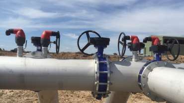
Setting a Bermad 750-66-B dual level infill float valve
![101_2721 Infill float valve]()
The Bermad 750-66-B dual level float valve is engineered for a variety of hydraulically operated applications within the waterworks industry. Colin Kirkland outlines Bermad’s best-practice procedure to select and set a valve for success.
The Bermad 750-66-B control valve is typically used to automatically fill elevated storage reservoirs or larger ground-level storage tanks. This valve can also be used in applications where there is a mechanical float located at water level—allowing the valve to open and close remotely.
To learn more about the operation and function of the valve, take a moment to view the animation below:
Installation of the valve
A key element of any control valve installation is the ability to isolate both the upstream and downstream sides of the valve. This ensures that, if required, the actuator can be removed without taking the tank out of action.
In order to carry out internal inspection of the product, isolation is required both before and after the control valve. The isolation valve on the outlet is often forgotten, and requires drainage of the downstream pipework for major maintenance. If this is not an issue, then the downstream valve does not have to be fitted.
A smaller bypass is also included to ensure that manual filling can continue during current or future maintenance periods.

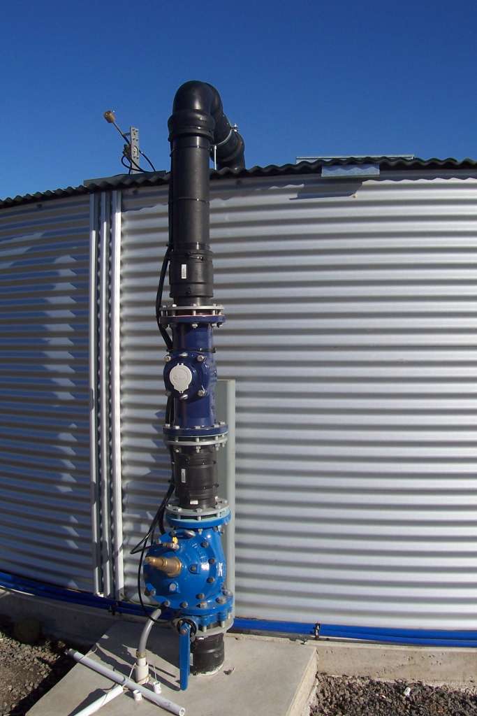
The Bermad 750-66-B control valve out on the field.
Connection of the float mechanism
To ensure the double chambered control valve can switch on and off, there are several control tubes that connect the valve to the float mechanism. These tubes should be 10mm in size or larger to avoid delays in valve operation.
In frost-prone regions, these tubes should either be lagged or fitted inside a conduit to avoid ice forming on the tubes.
The float mechanism is designed to include a mounting bracket, allowing the float to be secured to either the inside or outside of the tank. If there is any possibility of Internal or external waves within the tank, the float can be fitted inside sitting wells to ensure smooth performance.

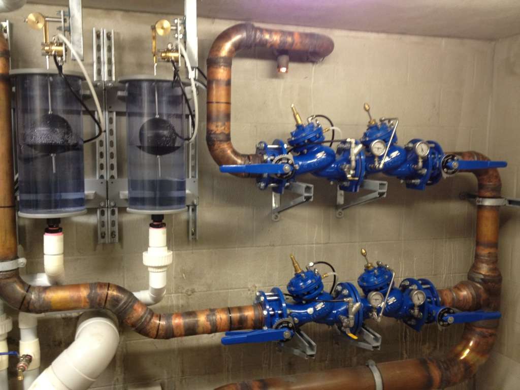
Sitting wells in application.
Setting the Bermad 750-66-B dual level float valve
It’s important that the setting procedure is completed accurately to ensure the reliability and performance of the valve. The following video demonstration has been produced to support engineers commissioning the valve on the field:
We’re here to help
Our team of dedicated staff are always prepared to find a solution. We offer extensive product information and engineering data on our product pages, which are available here.
If you require on field assistance, get in touch with our team via our live field support tool, or contact our team online.
Make enquiry
Online Enquiry Close
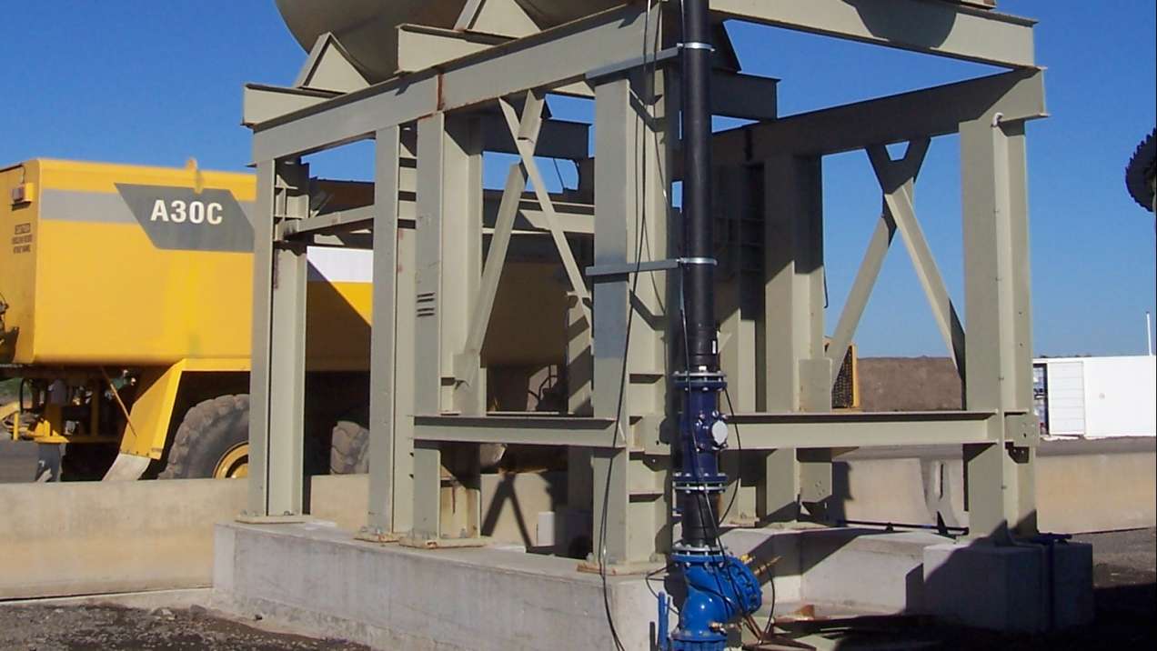
The Bermad 750-66-B dual level float valve is engineered for a variety of hydraulically operated applications within the waterworks industry. Colin Kirkland outlines Bermad’s best-practice procedure to select and set a valve for success.
The Bermad 750-66-B control valve is typically used to automatically fill elevated storage reservoirs or larger ground-level storage tanks. This valve can also be used in applications where there is a mechanical float located at water level—allowing the valve to open and close remotely.
To learn more about the operation and function of the valve, take a moment to view the animation below:
Installation of the valve
A key element of any control valve installation is the ability to isolate both the upstream and downstream sides of the valve. This ensures that, if required, the actuator can be removed without taking the tank out of action.
In order to carry out internal inspection of the product, isolation is required both before and after the control valve. The isolation valve on the outlet is often forgotten, and requires drainage of the downstream pipework for major maintenance. If this is not an issue, then the downstream valve does not have to be fitted.
A smaller bypass is also included to ensure that manual filling can continue during current or future maintenance periods.
The Bermad 750-66-B control valve out on the field.
Connection of the float mechanism
To ensure the double chambered control valve can switch on and off, there are several control tubes that connect the valve to the float mechanism. These tubes should be 10mm in size or larger to avoid delays in valve operation.
In frost-prone regions, these tubes should either be lagged or fitted inside a conduit to avoid ice forming on the tubes.
The float mechanism is designed to include a mounting bracket, allowing the float to be secured to either the inside or outside of the tank. If there is any possibility of Internal or external waves within the tank, the float can be fitted inside sitting wells to ensure smooth performance.
Sitting wells in application.
Setting the Bermad 750-66-B dual level float valve
It’s important that the setting procedure is completed accurately to ensure the reliability and performance of the valve. The following video demonstration has been produced to support engineers commissioning the valve on the field:
We’re here to help
Our team of dedicated staff are always prepared to find a solution. We offer extensive product information and engineering data on our product pages, which are available here.
If you require on field assistance, get in touch with our team via our live field support tool, or contact our team online.
Make enquiry
