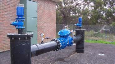
Pressure relief valve for pressure reducing system
![Pressure Reducing Valves_Header]()
This article will describe how to set a pressure relief valve—or PRV—in a pressure reducing station, with insights into sizing, best-practice locations for installation, and helpful accessories you can add to the valve.
In any pressure reducing station, it’s critical to ensure that the downstream pressure is kept at a constant in all flow conditions, regardless of demand.
Understanding the need for a pressure relief valve
In certain instances where there is a rapid reduction in flow, a pressure reducing valve (or PRV) can sometimes run slightly high in downstream pressure until the valve closes down.
In these cases, the inclusion of a pressure relief valve—set marginally higher than the pressure reduction valve—can safeguard the network against any higher-than-required pressures.
Additionally, during routine maintenance of a pressure reduction valve, there is a potential for inexperienced operators to inadvertently bring the pressure reduction valve back online, generating momentarily high-pressure conditions. The inclusion of a pressure relief valve can ensure the network remains safe in these instances.
Where should the pressure relief valve be installed?
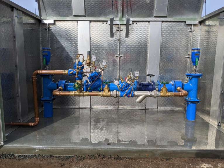
In most cases, the pressure relief valve is installed immediately downstream of the pressure reduction valve, on a tee branch off the side of the pipeline.
Typically, the relief valve should have its own independent isolation valve. This ensures online maintenance can be completed without stopping flow from the network.

How to size the pressure relief valve in the station
Typically, the pressure relief valve should be sized to ensure that any excess pressure is relieved in a rare event.
In any conditions where there is a very rapid reduction of flow in a network, the pressure reducing valve will see higher-than-normal-pressure and will subsequently begin to close in order to reduce the pressure.
The purpose of the pressure relief valve is to relieve any excess pressure which is around 5 to 10 metres above the set point of the valve.
Usually, the amount of discharge from the relief valve is minimal; this gives the pressure reducing valve a chance to close.
As the pressure relief valve usually relieves to atmosphere, the smaller the valve the faster it opens. There is no issue with the valve working with potentially very-high velocities for brief periods.
As a rule of thumb, it’s typically desirable for the relief valve to cope with around 25-30% of the pressure reduction valve flow, with relief velocities up to 7m/s.
For example, if a pressure reducing station had a flow of 5 to 50 l/s in a network, the ideal size of a relief valve will relieve a maximum of up to 15 l/s, which equates to valve size of about 50mm in size.
We must stress that any valve size should be selected in conjunction with the designer of the station. In rare instances, there are requirements that the valve must be able to cope with 100% of the design’s flow in the event of a catastrophic failure event.
Helpful accessories you can add to the relief valve
In many instances, the locations of the pressure releasing valves are in remote or isolated locations. Frequently, providers need to ability to quickly identify if the relief valve is open and relieving water. It may be that the PRV requires a service or needs a technician to visit and inspect the station.
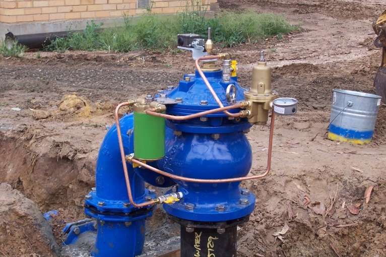
If telemetry is available, often a micro-switch can be fitted to provide instant feedback that the valve is open.

How to set the pressure relief valve
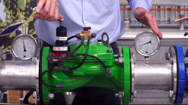
The following video highlights detailed best-practice for setting a pressure relief valve in a pressure reducing station.
If in any doubt—or for additional information and guidance—please do not hesitate to contact your nearest Bermad office.
Make enquiry
Online Enquiry Close
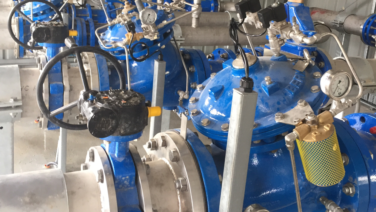
This article will describe how to set a pressure relief valve—or PRV—in a pressure reducing station, with insights into sizing, best-practice locations for installation, and helpful accessories you can add to the valve.
In any pressure reducing station, it’s critical to ensure that the downstream pressure is kept at a constant in all flow conditions, regardless of demand.
Understanding the need for a pressure relief valve
In certain instances where there is a rapid reduction in flow, a pressure reducing valve (or PRV) can sometimes run slightly high in downstream pressure until the valve closes down.
In these cases, the inclusion of a pressure relief valve—set marginally higher than the pressure reduction valve—can safeguard the network against any higher-than-required pressures.
Additionally, during routine maintenance of a pressure reduction valve, there is a potential for inexperienced operators to inadvertently bring the pressure reduction valve back online, generating momentarily high-pressure conditions. The inclusion of a pressure relief valve can ensure the network remains safe in these instances.
Where should the pressure relief valve be installed?
In most cases, the pressure relief valve is installed immediately downstream of the pressure reduction valve, on a tee branch off the side of the pipeline.
Typically, the relief valve should have its own independent isolation valve. This ensures online maintenance can be completed without stopping flow from the network.
How to size the pressure relief valve in the station
Typically, the pressure relief valve should be sized to ensure that any excess pressure is relieved in a rare event.
In any conditions where there is a very rapid reduction of flow in a network, the pressure reducing valve will see higher-than-normal-pressure and will subsequently begin to close in order to reduce the pressure.
The purpose of the pressure relief valve is to relieve any excess pressure which is around 5 to 10 metres above the set point of the valve.
Usually, the amount of discharge from the relief valve is minimal; this gives the pressure reducing valve a chance to close.
As the pressure relief valve usually relieves to atmosphere, the smaller the valve the faster it opens. There is no issue with the valve working with potentially very-high velocities for brief periods.
As a rule of thumb, it’s typically desirable for the relief valve to cope with around 25-30% of the pressure reduction valve flow, with relief velocities up to 7m/s.
For example, if a pressure reducing station had a flow of 5 to 50 l/s in a network, the ideal size of a relief valve will relieve a maximum of up to 15 l/s, which equates to valve size of about 50mm in size.
We must stress that any valve size should be selected in conjunction with the designer of the station. In rare instances, there are requirements that the valve must be able to cope with 100% of the design’s flow in the event of a catastrophic failure event.
Helpful accessories you can add to the relief valve
In many instances, the locations of the pressure releasing valves are in remote or isolated locations. Frequently, providers need to ability to quickly identify if the relief valve is open and relieving water. It may be that the PRV requires a service or needs a technician to visit and inspect the station.
If telemetry is available, often a micro-switch can be fitted to provide instant feedback that the valve is open.
How to set the pressure relief valve
The following video highlights detailed best-practice for setting a pressure relief valve in a pressure reducing station.
If in any doubt—or for additional information and guidance—please do not hesitate to contact your nearest Bermad office.
Make enquiry
